IEC 60309 connectors earn their reputation by reducing ambiguity in situations where mistakes can be expensive or dangerous. While color and pin configuration provide quick visual clues, the standard’s “clock position” adds a more decisive element: mechanical keying that helps prevent incompatible voltage systems from mating. We’ll explain how IEC 60309 “clock position” defines voltage ratings and how to use it correctly when specifying or troubleshooting industrial power connections.
What “Clock Position” Means in IEC 60309
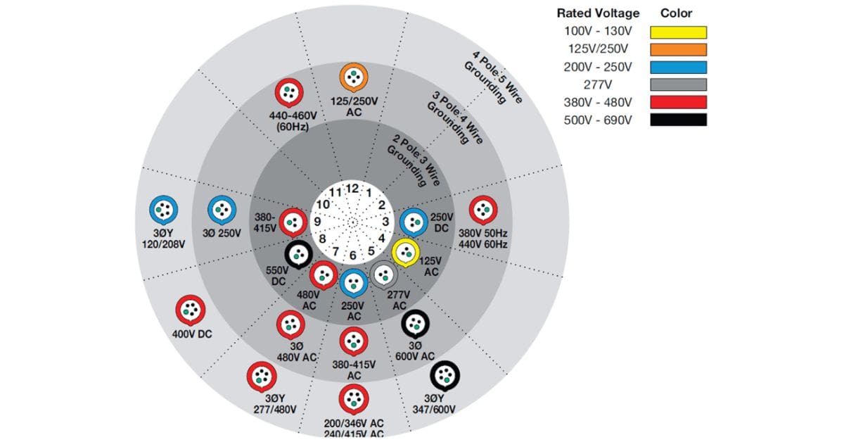
Clock position describes where the earth (ground) contact sits on the connector’s face when viewed as a clock dial. The standard uses that “clock face” as a reference so that the earth contact can be described at a specific hour position, such as 6 o’clock or 9 o’clock. That position is not cosmetic; it changes the physical geometry of the mating interface.
Because the earth contact’s position affects how the plug aligns with the socket, it becomes part of the connector’s keying system. If two connectors share the same current rating and the same number of pins but differ in clock position, they will not mate, preventing a mismatch.
Clocking Is a Voltage Identifier
Clock position matters because it works as a physical enforcement mechanism for electrical compatibility. Voltage rating influences insulation distances, design clearances, and what loads can safely receive power from a circuit. IEC 60309 reflects that reality by separating certain voltage categories through mechanical keying.
In the field, this distinction becomes practical. People move cord sets, borrow temporary power, and work under time pressure. A printed label can be missed, and colors can look similar under poor lighting. Clock position prevents the “it looks right” mistake from turning into an energized wrong connection.
The Earth Contact Sets the Reference Point
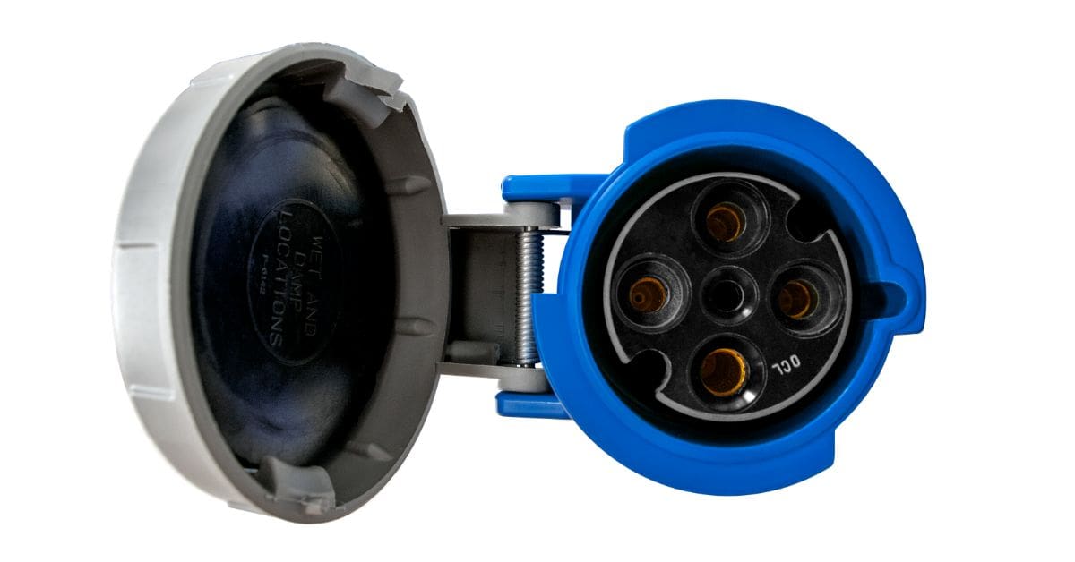
IEC 60309 typically uses the earth contact as the reference for clocking because it has a consistent safety function across systems. That consistent role makes it a stable anchor for orientation, even as pin counts and wiring schemes change between connector types. In other words, the standard can define clock positions in a way that remains meaningful across 2P+E, 3P+E, and 3P+N+E configurations.
Why the IEC 60309 System Needs Clocking
IEC 60309 is intended for environments that routinely operate multiple voltages and power sources. In those environments, visual similarity is a real hazard, not a theoretical one.
The Safety Problem Clocking Prevents
Mismating is the core problem clocking solves. If a plug intended for one voltage mates with a receptacle supplying a different voltage, the result can be immediate equipment damage, nuisance tripping, overheated components, or unsafe operating conditions.
Industrial sites also create the perfect conditions for these mistakes. Equipment gets moved, temporary drops appear during maintenance, and multiple contractors may work in the same area with different assumptions about what is “standard.” Clocking introduces a deliberate constraint that does not depend on memory, training, or careful reading under pressure.
How Clocking Works
Clock position is not the only mechanism IEC 60309 uses. Pin configuration creates a first layer of separation, because a 2P+E pattern cannot mate with a 3P+E or 3P+N+E pattern. That separation is helpful, but it does not fully solve the problem, because facilities can run multiple voltage systems that share the same basic pin pattern.
Clocking adds the next layer. By rotating the earth contact to different hour positions, the standard changes the mating geometry even when the pin count and shell size are similar. The connector housing, keyways, and pin alignment work together so that correct systems mate smoothly while incorrect combinations simply refuse to seat.
What Clocking Does
Color coding helps people move faster and work more confidently, but it has limits. Colors can fade, get dirty, or look different under harsh lighting. People can also misinterpret what a color “usually” means, especially if they have experience from another site with different conventions.
Clocking addresses the failure mode that color cannot. It blocks incompatible systems mechanically. That matters in mixed-voltage environments where some connectors may look close in size and shape, and where the consequences of a wrong connection can reach far beyond the point of use.
How Clock Position Maps to Voltage Ratings in Practice
Clock position functions as a compatibility gate that aligns with standardized voltage categories. In practice, it helps distinguish connectors that might otherwise appear similar in amperage and configuration.
How Voltage Categories Connect to Clock Positions
IEC 60309 uses clock positions to separate connectors associated with different voltage categories so they do not interchange. The exact mapping depends on the connector family and the configuration in question, but the functional intent is consistent: one category cannot mate with a receptacle intended for another.
Many facilities operate multiple supplies in ranges that can appear “close enough” at a glance, such as single-phase systems feeding portable loads alongside three-phase systems feeding larger equipment. Clocking provides mechanical confirmation that the connector is rated for the intended voltage category for that circuit.
When Color and Amperage Seem to Overlap
Two connectors can share an amperage rating and still represent different electrical systems, because amperage describes current capacity, not supply type. In some environments, connectors may also share similar housing colors or sit within the same general voltage family, which can make visual identification less reliable than teams expect.
In those moments, clock position is the more precise cue because it is engineered to prevent interchange. If the connector fits, the system is at least aligned on configuration and keying. If it does not fit, you have a clear signal to stop and verify before energizing anything.
How To Interpret Clocking in Mixed-Voltage Areas
Mixed-voltage areas demand discipline. Clocking reduces the chance of error, but good practice still matters because people can introduce exceptions through uncontrolled adapters, mislabeled receptacles, or nonstandard replacements. The safest approach is to treat clock position as one verification step in a chain.
Confirm the circuit supply at the source, not only at the receptacle face. Next, confirm connector markings and part numbers. Then use the clock position as a mechanical check to support what your documentation already says. When all three agree, you can then move forward confidently.
A Crucial Safety Layer
Clock position turns IEC 60309 from a set of labels into a system that actively prevents common mistakes. It works with pin configuration, markings, and color to reduce the risk of incorrect-voltage connections in real facilities where time pressure and equipment movement are common.
The main reason IEC 60309 “clock position” defines voltage ratings is how it makes the correct connection straightforward and makes the wrong connection difficult, adding a crucial safety layer that can otherwise lead to dangerous incidents.
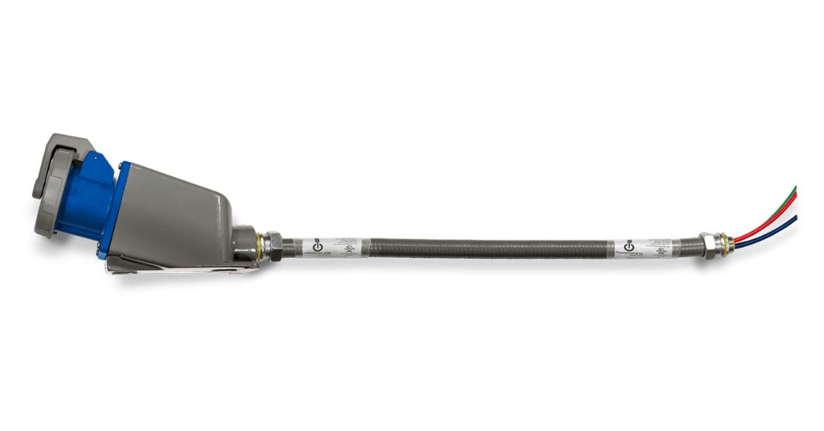
Electrol Powerwhips offers a durable IEC 60309, designed to meet the standard’s clock-position keying requirements, so the right plug mates with the right voltage every time. For multi-voltage environments where uptime and safety depend on proper connections, our prefabricated cords help you standardize, reduce mismating risk, and maintain consistent power distribution across the site. Contact us today!