Electrical systems demand precise diagnostics to ensure safe and efficient operations. When power cables fail, the consequences can range from minor equipment malfunctions to catastrophic system failures that pose serious safety risks. Diagnosing IEC power-cable continuity and voltage drop is a preventive maintenance protocol that protects both equipment and personnel from electrical hazards.
IEC power cables serve as the critical link between power sources and electrical devices across industrial, commercial, and residential applications. These standardized cables must maintain electrical integrity throughout their service life. Yet, they face constant stress from environmental factors, mechanical wear, and electrical loads that can compromise their performance over time.
Understanding the proper diagnostic techniques empowers maintenance teams to make informed decisions about cable replacement, system upgrades, and safety protocols that keep operations running smoothly.
What Are the IEC Power-Cable Standards?
IEC power cables conform to International Electrotechnical Commission specifications that govern construction, performance, and safety characteristics. IEC International Standards ensure consistent quality across manufacturers while establishing clear testing parameters for field diagnostics.
The IEC 60320 family of standards defines connector configurations, current ratings, and voltage specifications for detachable power cords commonly used in electronic equipment. Meanwhile, IEC 60227 and IEC 60245 establish requirements for fixed installation cables that carry power throughout building electrical systems.
Cable construction typically includes multiple copper conductors surrounded by insulation materials rated for specific voltage and temperature ranges. The outer jacket provides mechanical protection while maintaining flexibility for installation and service access. Understanding these details helps technicians identify potential failure points during diagnostic procedures.
Essential Testing Equipment and Safety Protocols
Accurate cable diagnostics require specialized test instruments designed for electrical measurements. Digital multimeters capable of measuring resistance, voltage, and current form the basic toolkit, while more advanced applications may require dedicated cable testers with automated sequence capabilities.
Safety protocols must also precede all testing activities to protect personnel from electrical hazards. Power systems should be de-energized and locked out according to established procedures before beginning diagnostic work. In addition, technicians should always wear personal protective equipment, including insulated gloves, safety glasses, and arc-rated clothing.
Conduct regular calibration schedules aligned with manufacturer recommendations to maintain instrument precision throughout their service life. Also, adhere to proper storage and handling practices to protect sensitive electronic components from damage.
Continuity Testing Procedures
Continuity testing verifies that electrical pathways remain intact throughout the cable length. This fundamental test identifies open circuits caused by conductor breaks, loose connections, or damaged terminations that prevent current flow. Testing procedures begin with complete system isolation to ensure safe working conditions.
Afterward, test leads connect between corresponding conductors at opposite cable ends, while the multimeter measures resistance values that indicate circuit integrity. Healthy conductors typically show resistance values below one ohm, depending on cable length and conductor size. Intermittent faults present unique diagnostic challenges since they may not appear during static testing conditions. Flexing the cable during continuity measurements can reveal loose connections or damaged conductors that fail under mechanical stress.
Voltage-Drop Analysis Techniques
Voltage-drop measurements quantify the electrical losses that occur as current flows through cable conductors. Excessive voltage drop indicates increased resistance that can cause equipment malfunction, reduced efficiency, and even potential safety hazards. Measurement techniques involve applying a known load current while monitoring voltage levels at both cable ends.
The difference between source voltage and load voltage represents the total voltage drop, which should remain within acceptable limits specified by electrical codes and equipment manufacturers. Cable length, conductor size, and load current directly influence voltage-drop calculations. Longer cables with smaller conductors may exhibit higher resistance, which increases voltage drop under identical load conditions. Proper cable sizing during initial installation prevents excessive voltage drop that could otherwise compromise system performance.
Common Cable Faults and Their Indicators
Insulation degradation represents one of the most serious cable faults since it can lead to ground faults, short circuits, and electrical fires. Insulation resistance testing using megohmmeter instruments reveals deterioration that may not be apparent through visual inspection.
Conductor corrosion develops gradually in environments with high humidity, chemical exposure, or galvanic action between dissimilar metals. Resistance measurements show increasing value over time as corrosion reduces the effective conductor cross-sectional area.
Mechanical damage from installation stress, vibration, or physical impact can also cause conductor breaks or insulation punctures, which may develop slowly or appear suddenly, depending on the severity of the mechanical forces involved.
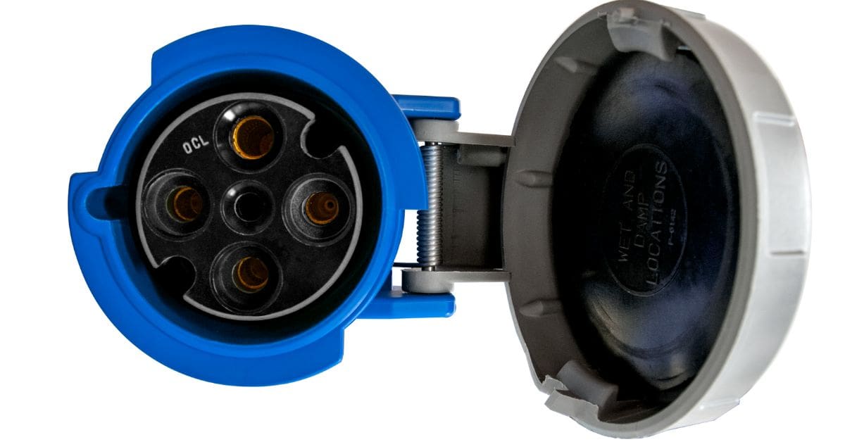
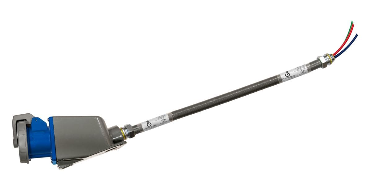
Electrol Powerwhips provides a dependable and durable solution with its IEC 60309 receptacle, designed to meet even the most demanding operational requirements. Built for heavy-duty performance, this receptacle ensures reliable power distribution, making it an ideal choice for industrial and commercial applications.
Interpreting Test Results
Test data interpretation requires understanding normal parameter ranges and recognizing patterns that indicate developing problems. Baseline measurements taken during initial installation are good reference points for comparison during subsequent testing cycles.
Trending analysis also reveals gradual changes that may not trigger immediate alarms but indicate deteriorating conditions requiring attention. Plotting resistance, voltage drop, and insulation resistance values over time helps identify maintenance intervals and replacement schedules.
Having accurate and updated documentation ensures consistent data collection and analysis procedures across different technicians and testing periods. Standardized forms capture essential information, including test conditions, instrument specifications, and environmental factors that may influence results.
Preventive Maintenance Strategies
Regular testing schedules based on equipment criticality, environmental conditions, and manufacturer recommendations enable maintenance teams to identify problems before they cause system failures. High-priority circuits may require monthly or quarterly testing, while less critical applications might use annual inspection cycles.
Environmental monitoring provides additional information on factors that accelerate cable degradation. Data on temperature, humidity, vibration, and chemical exposure levels help technicians establish appropriate testing frequencies and identify cables at higher risk for premature failure.
Advanced Diagnostic Technologies
Time domain reflectometry uses high-frequency pulses to locate faults along cable runs with precision measurement capabilities. This advanced technique proves especially valuable for long cables or installations where physical access limitations complicate traditional testing methods.
Thermal Imaging
Thermal imaging cameras can detect hot spots that indicate high-resistance connections or overloaded conductors. Regular thermal surveys support electrical testing by identifying problems that may not appear during static resistance measurements.
Partial Discharge Testing
Partial discharge testing, on the other hand, reveals insulation weaknesses that could lead to complete failure under operating conditions. This specialized technique requires sophisticated equipment but provides early warning of insulation deterioration in critical applications.
Making Informed Maintenance Decisions
Professional maintenance programs rely on comprehensive testing data to make informed decisions about cable replacement, system upgrades, and safety improvements. Diagnosing IEC power-cable continuity and voltage-drop measurements provides the technical foundation for critical decisions that impact operational reliability and personnel safety. Conducting regular testing schedules and employing proper diagnostic techniques ensures electrical systems maintain peak performance while minimizing the risk of unexpected failures during operation.