
Grounding electrode conductor sizing becomes much easier once you understand the reasoning behind the rules. Service conductors set the initial sizing requirement, but they don’t always determine the final conductor size. The grounding electrode itself can change what the installation requires.
Work through the system in a logical order. Begin with the conductors supplying the service. From there, consider the grounding electrode and determine whether its characteristics allow a different conductor size. Here are some general grounding electrode conductor sizing guidelines your team can follow.
Start With the Conductor
Before selecting a conductor size, first identify the conductor’s purpose. A grounding electrode conductor, commonly called a GEC, connects the electrical system to the grounding electrode system. That system can include electrodes such as structural metal, concrete-encased electrodes, ground rings, or ground rods.
An equipment grounding conductor performs a different function. It provides a conductive path that supports fault clearing when energized equipment develops a ground fault. Because these conductors perform different jobs, the NEC uses different methods to size them.
Use the Service Conductors as the Baseline
After confirming that the conductor is a GEC, look at the largest ungrounded service-entrance conductor. In practical terms, that means looking at the conductors carrying power into the service. Their size establishes the baseline for the grounding electrode conductor.
The NEC groups service conductor sizes into ranges. As service conductors increase, the required GEC increases at defined points rather than changing with every conductor size.
For example, 2/0 or 3/0 copper service conductors correspond to a 4 AWG copper GEC under the general sizing method. Larger service conductors eventually require a larger grounding electrode conductor.
However, this is only the first step. The electrode type can still affect the final requirement.
Do Not Size the GEC From the Breaker
Service ampacity provides useful system information, but it does not directly determine the GEC size. The actual ungrounded service conductors control the general calculation.
Conductor material and system design can change the conductor size used for a particular service. Two installations with similar ampere ratings do not always use identical service conductors.
Account for Parallel Conductors Correctly
Larger services frequently use conductors in parallel. In that case, looking at one conductor from the parallel set does not provide a complete basis for sizing. Instead, consider the combined circular-mil area of the parallel conductors for one phase.
Suppose two conductors operate together to carry the same phase. Their combined area represents the effective conductor size used to determine the GEC requirement. Considering only one would understate the service-path size.
Once the equivalent area is established, it can be used to determine the general grounding electrode conductor size. The principle is straightforward: when several conductors work together electrically, the GEC calculation needs to reflect their combined size.
Let the Electrode Influence the Final Size
After establishing the general conductor size, identify the grounding electrode.
Before finalizing a grounding electrode conductor, review:
- Size of the ungrounded service conductors
- Parallel conductor arrangements
- General GEC size based on the service
- Type of grounding electrode
- Path of the grounding electrode conductor
- Conductor material
- Physical installation conditions
- NEC edition adopted for the project
With those details established, justifying the final conductor size becomes much easier.
Understand Why Ground Rods Often Stop at 6 AWG Copper
Ground rods provide one of the clearest examples of an electrode-specific sizing limit. Consider a large service where the general calculation calls for a 2 AWG copper grounding electrode conductor. If a section of that conductor serves only qualifying rod, pipe, or plate electrodes, the NEC does not require that portion to continue increasing with the service size.
For the applicable rod connection, 6 AWG copper generally represents the largest conductor the NEC requires. The reasoning centers on the electrode’s performance. Once the conductor reaches that size, adding more copper does not provide enough additional grounding benefit to require further increases.
The 6 AWG Limit Does Not Apply to Every GEC
The grounding electrode system must still be considered as a complete path. If the conductor serving the rods continues to another electrode that requires a larger size, the 6 AWG allowance cannot automatically extend through the entire system.
Treat Concrete-Encased Electrodes and Ground Rings Separately
Concrete-encased electrodes follow a different sizing principle. When the applicable conditions are met, a grounding electrode conductor serving a qualifying concrete-encased electrode does not need to be larger than 4 AWG copper. This arrangement appears frequently in new construction where the foundation incorporates the grounding electrode.
Ground rings follow another approach. A ground ring uses bare copper buried around a building or structure to establish a grounding electrode. The ring itself must use at least 2 AWG copper. For the conductor connecting to the ground ring, the NEC does not require the GEC to be larger than the ring conductor.
These examples show why electrode type remains essential to the sizing decision. The general service-based calculation establishes the starting point, while the electrode determines whether a different upper limit applies.
Consider Material and Installation Conditions
Conductor size alone does not complete the design. Copper remains common for grounding electrode conductors because it performs well across a wide range of grounding applications.
Aluminum and copper-clad aluminum can also be permitted, but their installation requires additional consideration. Exposure to conditions that promote corrosion creates particular concerns.
The physical route also matters. A GEC that faces mechanical damage needs suitable protection. Connection methods must remain compatible with the conductor and electrode materials.
Use a Repeatable Sizing Process
General grounding electrode conductor sizing guidelines don’t require memorizing every conductor combination. A repeatable process provides a stronger approach.
First, identify the conductor as a GEC. Then determine the size and material of the largest ungrounded service conductors. For parallel services, account for the combined conductor area before establishing the general GEC requirement. Next, identify the electrode that the conductor serves.
Finally, review how the conductor will be installed. Material restrictions and physical protection remain important even after the correct size has been established.
Carry Grounding Continuity Through the Equipment Connection
Proper grounding does not end once the grounding electrode conductor reaches the service. The equipment grounding path must remain continuous as power moves toward the connected load.
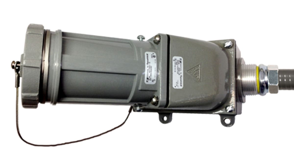
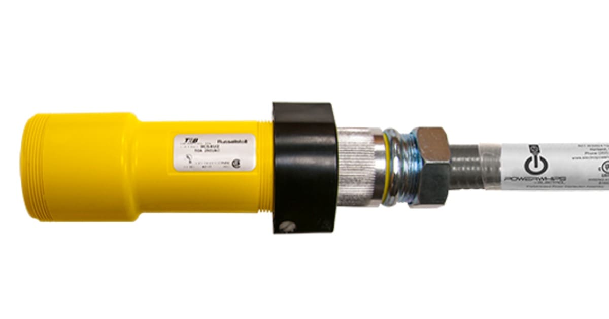
That is where connector design becomes important. Russellstoll pin-and-sleeve connections use dedicated grounding contacts that establish the ground connection before the current-carrying contacts engage. The grounding path remains connected until after those contacts separate.
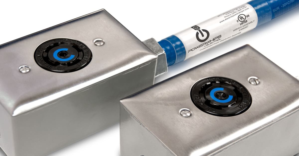
Electrol PowerWhips offers Russellstoll connector options for demanding electrical applications where secure grounding and dependable equipment connections are crucial. The right connector helps maintain the equipment grounding path through the final connection while supporting the integrity of the broader power system. Contact Electrol PowerWhips to discuss a power solution that supports reliable long-term performance.